Mechanical design development study based on project “Stress analysis of a mounting plate“.
Introduction:
Mechanical stress analysis is a branch of engineering that involves evaluating and predicting the distribution of forces and deformations within a structure or component under various loading conditions. This analysis helps engineers assess the structural integrity of a design, ensuring that it can withstand external forces and environmental conditions without failure.
By applying principles of physics and material science, stress analysis aims to identify areas of potential weakness, deformation, or failure in a mechanical system. Engineers use mathematical models, simulation tools, and experimental methods to analyze how different materials and structures respond to applied loads, enabling them to optimize designs for safety, performance, and durability in a wide range of applications such as bridges, buildings, automotive components, and aerospace structures.
Siemens NX is a comprehensive integrated computer-aided design (CAD), computer-aided manufacturing (CAM), and computer-aided engineering (CAE) software suite which has a simulation tool to conduct mechanical stress analysis.
Analyzing the results:
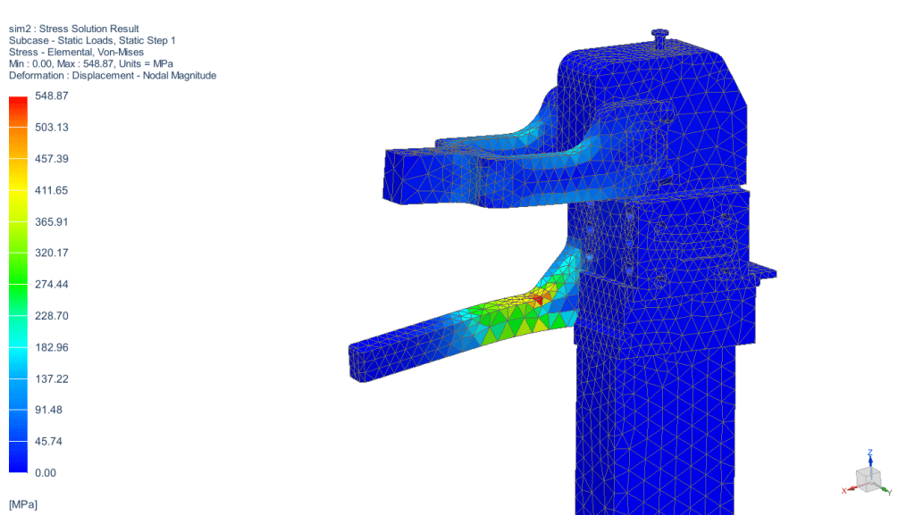
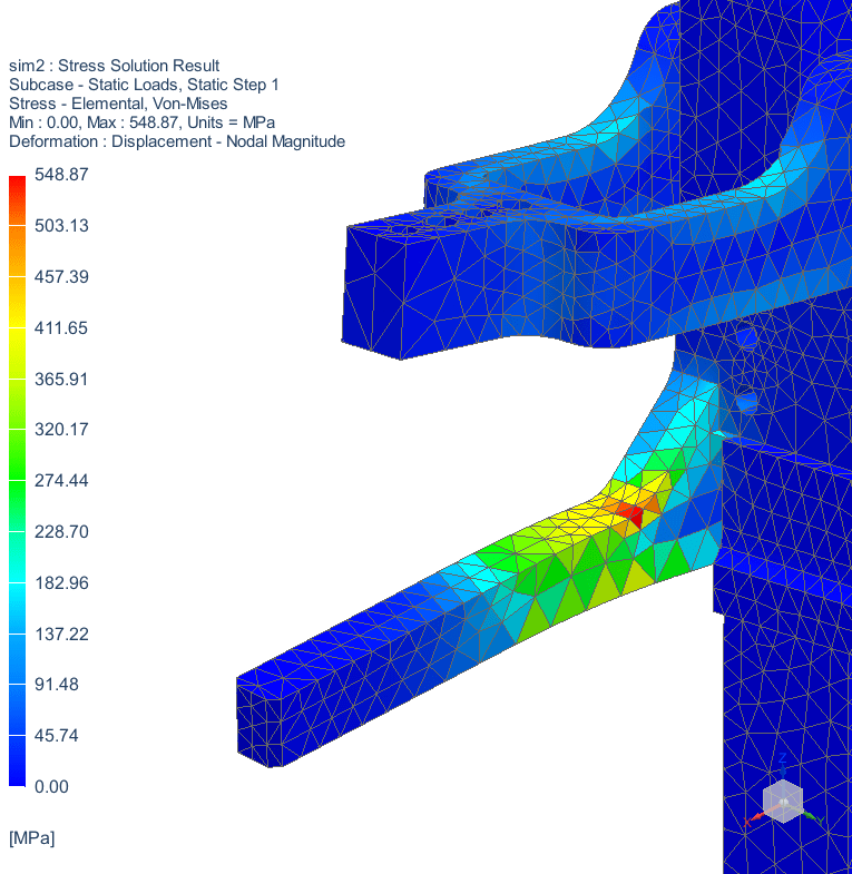
In the stress analysis project of the clamp mounting plate, we had simulated the stress under a reaction force of 2454N and we had found the weak point of the plate and the maximum value of the stress, 548 MPa, which occurs in the red area below.
To analyze if this is an acceptable value or not, we need to check the material properties of the steel plate. In steel structures, the one of the most important properties of the steel is yield strength.
| Material | Yield Strength [MPa] |
|---|---|
| S355-J2 structural steel | 355 |
We can see from the table that S355-J2 structural steel´s yield strength is 355MPa. This is the stress value where the material will begin permanent deformation, which is not a desired thing.
Allowable working stress
When we design a steel part under load, we need to keep the stress below the yield strength. But, in addition to this value, we must also set a safety factor because the materials have their own internal imperfections. Additionally, simulation software also has its own calculation errors.
There are several ways to define a safety factor based on engineering standards, codes, or industry best practices. Common safety factors for steel components typically range from 1,5 to 3. Factors toward the higher end of the range are used for critical applications or when there is significant uncertainty. If the design were used in such applications where a failure could cause serious hazards, this safety factor could be a lot higher. For example, cables in an elevator must have a safety factor of 11.
Let’s assume that safety factor is 1,5 in this application. Hence, the allowable working stress is:
355/1,5=236MPa.
We can clearly see that this application is not safe because the occurring stress is bigger than allowable stress (548>236). In other words, the plate will not carry the load in its allowable working range and there will be a permanent deformation in the red area. So, we must improve the design.
1st improvement idea: Increasing the material thickness:
A thicker material can often carry a higher load before reaching its yield point compared to a thinner material of the same type. This is because the cross-sectional area of the thicker material is greater, resulting in higher load-carrying capacity.
Let’s increase the plate thickness from 12mm to 20mm and run the simulation test again. Here are the results:
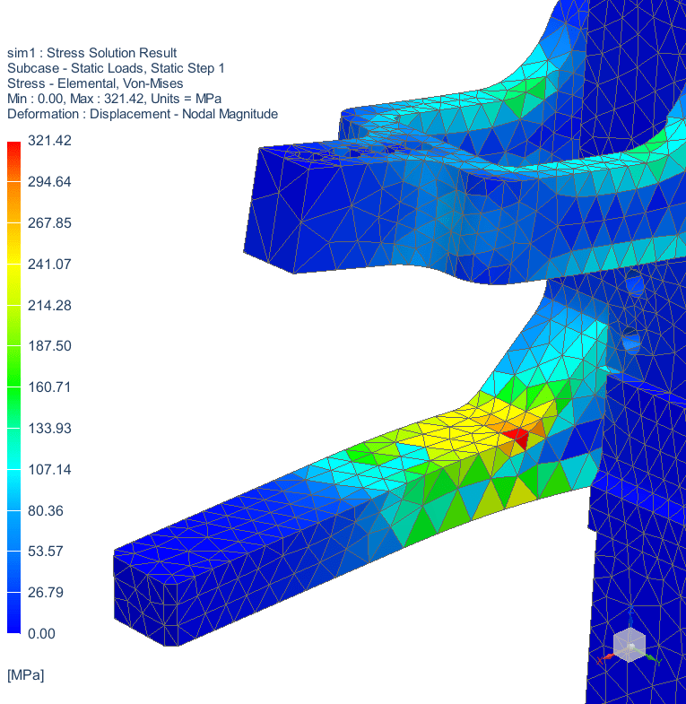
As seen, increasing the material thickness reduced the max stress in the red area to 321MPa. But this is still larger than the allowable working stress and we can still improve it.
2nd Improvement idea: Adding a second mounting plate to the other side of the clamp, with original thickness (12mm):
Adding a second mounting plate to the other side of the clamp will eliminate the torsion at the previous red area and the force will be shared equally between plates. Eventually, the stress will decrease significantly.
Let’s add the second plate in CAD, update the parameters and run the simulation again. Here are the results:
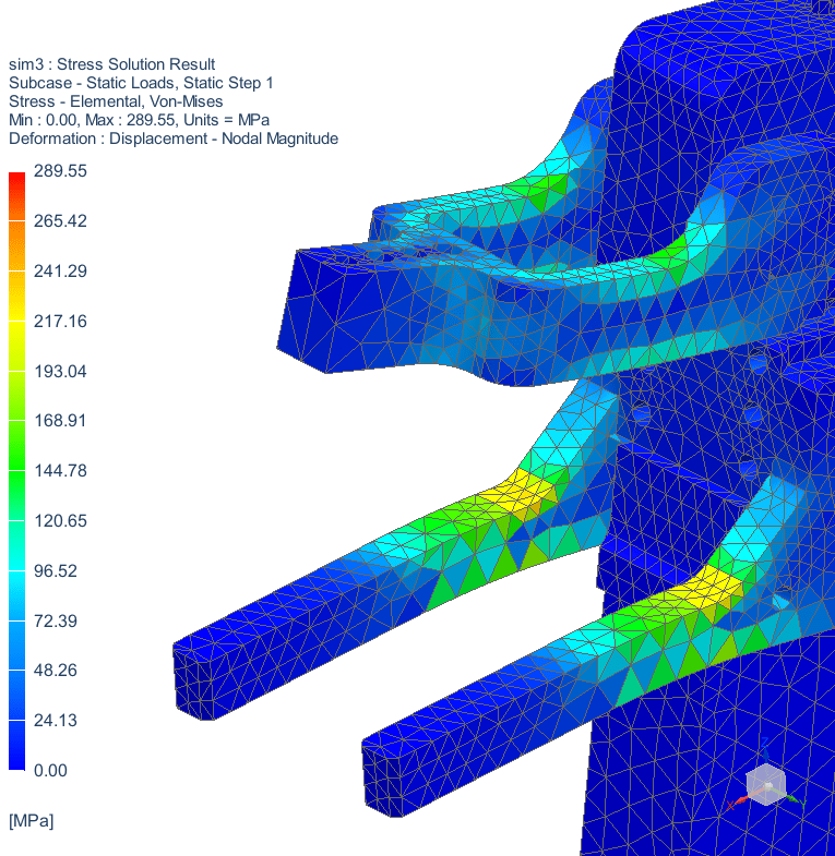
It can be seen from the results that the stress is shared between plates equally and it occurs in the yellow area the most which is about 217MPa. This value is smaller than the allowable working stress, 236MPa. So, this solution is the safest solution to go in this application.
Design 1
One side mounting plate, 12mm.
Max stress: 548MPa
Design 2
One side mounting plate, 20mm.
Max stress: 321MPa
Design 3
Two sides mounting plate, 12mm.
Max stress: 217MPa

Leave a comment