
There might be several reasons why one might need to wire a custom connector to a cable. Equipment from different manufacturers may use proprietary connectors or have unique pin configurations. If you need to connect components from different sources, a custom connector may be necessary to ensure compatibility.
Also, when integrating new equipment or components into an existing system, it’s possible that the existing connectors and cables are not directly compatible. A custom connector can serve as an adapter, allowing seamless integration without the need for extensive modifications.
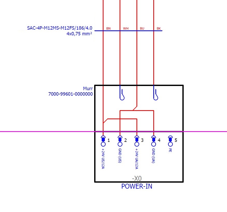
Additionally, pin configuration of the voltage at source can be different from the configuration at target. In this case a specific wire pin might be needed to transfer from a pin to another, or similarly, it might be necessary to jump it to another wire so that same voltage or ground is available at both wires.
How to wire a connector to a cable?
Wiring a connector to a cable according to an electrical plan requires careful attention to detail to ensure a safe and reliable connection. Here are some important instructions to apply:
1. Follow the Electrical Plan:
Carefully review the electrical plan and identify the correct connector and cable types specified.
2. Connector Compatibility:
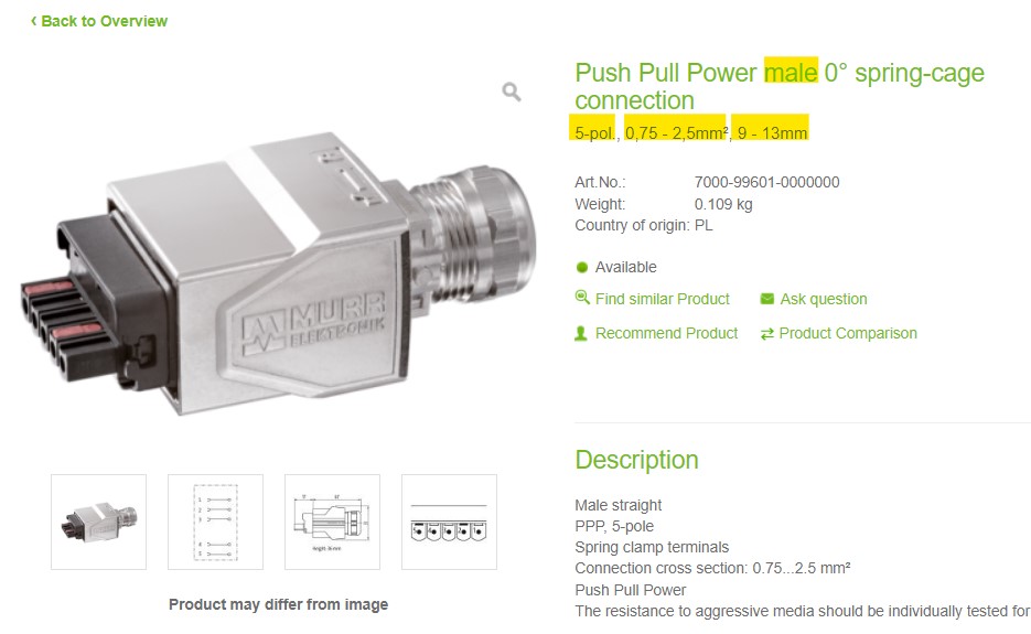
Ensure that the connector you are using is compatible with the cable type and meets the requirements specified in the electrical plan. Important features to check are coding, number of pins, gender, wire cross section range, cable diameter range and possible certificates or approvals.
3. Cable Preparation:
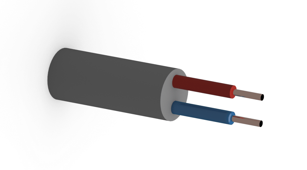
Strip the cable insulation carefully to expose the required length of conductor. If necessary or required, use ferrules at the end of the wires. Use the appropriate tools to avoid damaging the conductors.
4. Correct Wire Termination:
Make sure to terminate each wire in the correct pin or terminal of the connector according to the electrical plan. Follow the color-coding and labeling conventions specified in the plan.
5. Secure Connections:
Use proper crimping, screwing, or soldering techniques to secure the connections between the cable conductors and the connector pins. Ensure that the connections are tight and reliable.
6. Strain Relief:
Provide strain relief for the cable near the connector to prevent tension on the wires. This helps prevent damage to the connections due to pulling or bending of the cable.
7. Insulation and Shielding:
If the cable has shielding or insulation, make sure to follow the plan’s instructions regarding the termination of these elements. Proper grounding and insulation are crucial for safety and performance.
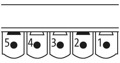
8. Polarity and Orientation:
Pay attention to the polarity and orientation specified in the electrical plan. Even though almost all the standard connectors have a special coding to avoid mis-mating (see the post M12 connectors and their coding types), some connectors may have specific requirements for the arrangement of positive and negative connections.
9. Testing:
After the wiring is complete, perform continuity checks and other relevant tests to ensure that the connections are correct and that there are no short circuits or open circuits.
10. Documentation:
Keep detailed records of the wiring process, including connector types, pin assignments, and any deviations from the original plan and report it to the e-plan designer. This documentation can be valuable for troubleshooting and future maintenance.
11. Compliance with Standards:
Ensure that the wiring and connections comply with relevant electrical standards and regulations. This is crucial for safety and to meet legal requirements.
Always exercise caution when working with electricity, and if you are unsure about any aspect of the wiring process, consult with a qualified electrician or follow the guidance of the electrical plan designer.

Leave a comment